Introduction
This engineering bulletin briefly examines how the addition of microsilica to concrete can help protect the reinforcement against chloride-induced corrosion. A description of the reinforcement corrosion process is given. Laboratory studies and field data are used to quantify corrosion test results and better explain protection requirements. Microsilica, also known as silica fume or condensed silica fume, is available as a dry powder, a densified powder or as a liquid slurry admixture.
The Chloride-Induced Corrosion Process
The chloride-induced corrosion of reinforcement in concrete is an electrochemical process caused by chlorides which migrate through the pores of the concrete to attack the steel. The alkaline environment of concrete creates a thin, passivating layer around all the embedded steel. Chlorides attack the steel through defects in this protective barrier to start the corrosion process. Iron at the anode (usually the top mat of reinforcement in a slab) chemically combines with the chloride ion and eventually becomes the corrosion product, ferric oxide (Fe2O3). Buildup of ferric oxide causes staining and cracking of the concrete. During this corrosion process, electrons are released and travel to the cathodic steel to form hydroxl ions (OH –). The cathode is located where there is good access to oxygen, usually the bottom mat of reinforcement in a slab. The hydroxl ions travel through the concrete to the anodic steel, completing the corrosion process. Chlorides are available primarily from deicing salts and marine environments. Clearly if the permeability of the concrete were significantly reduced, it would take longer for chlorides to travel from the concrete surface to the reinforcement. This would increase the time to corrosion-initiation and extend the service life of the structure. Also if the resistivity of the concrete were increased, the corrosion process could be slowed even if chlorides reach the reinforcement.
Concrete Permeability
When cement combines with water the resulting chemical reaction forms calcium silicate hydrate (CSH) “glue” and calcium hydroxide. The CSH binds the aggregate together while the crystalline calcium hydroxide simply occupies space and contributes to a weaker and more permeable concrete matrix. Microsilica consists primarily of silicon dioxide (SiO2) which, when added to fresh concrete during the batching process, chemically combines with the calcium hydroxide to form more CSH. See the GCP Applied Technologies Technical Bulletin TB-0709 “FORCE 10,000® D Microsilica and its Uses in Concrete” for a more complete explanation. Additionally, microsilica is roughly one-one hundredth the size of a cement grain which helps to fill in the voids between the larger CSH particles and the aggregate. The addition of microsilica to the concrete mix results in significantly less permeable matrix.
The most common test methods used to evaluate the chloride permeability are AASHTO T-277 “Rapid Determination of the Chloride Permeability of Concrete”1 and ASTM C 1202 “Standard Test Method for the Electrical Indication of Concrete’s Ability to Resist Chloride Penetration.”
Both tests are quick methods for determining concrete chloride permeability for research and ongoing construction projects. These tests do not measure the actual permeability but rather the resistivity of the concrete, which has a good inverse correlation with concrete permeability. Although there are some subtle differences between the two test methods, they both subject a 60 volt potential to a 4 in. (100 mm) diameter by 2 in. (50 mm.) thick specimen for 6 hours and measure the cumulative electrical charge passed in coulombs. AASHTO anticipates a precision variability of 19.5% while ASTM allows greater variability.
There are at least a dozen parameters which can affect the final coulomb reading, so an exact, reproducible test measurement is nearly impossible. Five chloride permeability categories were, therefore, created as shown in Table 1. Concretes with coulomb readings in the same category are considered to have equivalent chloride permeability. Design engineers who specify microsilica generally require a coulomb reading in the 100 to 1,000 coulomb category which is classified as “very low”.
Table 1
AASHTO T-277 Chloride Permeability
Based on Charge Passed
| Charge Passed (coulombs) |
Chloride Permeability |
Typical of |
| >4,000 | High | High water/cement ratio (>0.6). Conventional PCC. |
| 2,000 - 4,000 | Moderate | Moderate water/cement ratio (0.4 - 0.5).Conventional PCC. |
| 1,000 - 2,000 | Low | Low water/cement ratio (<0.4). Conventional PCC. |
| 100 - 1,000 | Very Low | 1200 |
| <100 | Negligible | 1800 |
It is recommended that test specimens be 4 x 8 in. (100 x 200 mm) cylinders cast from a ready-mix truck at the job site according to ASTM C 31 and cured for 90 days prior to testing. Some engineers believe inaccuracies exist in the FHWA rapid permeability test method and are specifying “percent microsilica by weight of cement” rather than coulomb levels. Usually a specified microsilica quantity is based on the severity of the service environment. Two common microsilica dosage rates are 7.5% by weight of cement in parking structures and 10% for piles in a marine environment. Combining microsilica with other corrosion protection systems, such as DCI® Corrosion Inhibitor; is also a common practice.
Laboratory and field tests 2, 3, 4, 5, 6 have been performed to measure the effect of microsilica dosage rates on the permeability of concrete. Figure 1 shows the results of these studies utilizing a 650 lbs/yd3 (385 kg/m3) cement factor mix at a 0.40 water/cement ratio after 90 days of curing. Two points are apparent from this figure:
- As more microsilica is added to the concrete the chloride permeability (as measured in coulombs) is reduced; and
- The coulombs measured usually vary for samples of the same mix design.
The actual coulomb test result is very dependent on the concrete materials used, microsilica amount and testing accuracy.
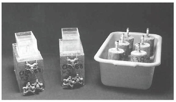
A method used by GCP Applied Technologies to determine actual chloride ingress into concrete with and without microsilica consists of cyclic ponding of concrete blocks and “lollipops” (Figure 2) with a sodium chloride solution for extended lengths of time. These ongoing tests6, performed at GCP Applied Technologies, measure actual chloride contents in the concrete as a function of time, mix design and depth in the concrete. From these data, the actual chloride permeability of the concrete can be measured as an effective diffusion coefficient. These are compared to AASHTO T-277 results in Table 2. Using these diffusion coefficients and further calculations, GCP has been able to estimate the amount of chloride reaching the reinforcement in certain structures as a function of time. See your GCP representative for further details.
Table 2
Effective Diffusion Coefficients vs AASHTO T-277 Results
| Mix | Water/Cement Ratio | Microsilica (%) | 28-Day AASHTO T-277 (coulombs) |
Effective Diffusion Coefficient (10-8 cm2/sec) |
| A | 0.48 | 0.0 | 3,700 | 9. |
| B | 0.48 | 15.0 | 225 | 0.6 |
| C | 0.43 | 7.5 | 380 | 0.8. |
| D | 0.38 | 0.0 | 2,660 | 2 |
| E | 0.38 | 15.0 | 100 | 0.3 |
Cement Factor: 355 kg/m3 (600 lbs/yd3)
Figure 1
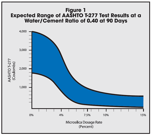
Figure 2
This chloride ponding test data proves that as more microsilica is added to a constant mix design, the concrete chloride permeability is reduced. These data also qualitatively agree with the AASHTO T-277 test method which states that as the coulombs measured decrease, the chloride permeability also decreases.
Concrete Resistivity
Concrete resistivity, the resistance of concrete to the passage of a corrosion induced electrical current, is also an index of corrosion protection. In a concrete structure when chlorides attack the reinforcement, electrons are released at the anode and travel via the steel to the cathode. At the cathode, hydroxl ions are produced which travel to the anode through the concrete to complete the corrosion circuit. Macrocell corrosion takes place between an anode and cathode separated by a large distance such as a top and bottom mat of reinforcement in a slab. By increasing the resistivity of the concrete, the process of macrocell corrosion may be slowed but not stopped. Microcell corrosion is defined as that which takes place when the anode and cathode are adjacent to each other on the same reinforcement. Microcell corrosion is usually not affected by increased concrete resistivity and may be less severe than macrocell corrosion. The addition of microsilica
Table 3
Concrete Properties
| Mix # | Water/Cement Ratio | Microsilica by Mass of Cement* (%) |
28-Day Compresive Strength | 28-Day Chloride Permeability (coulombs) |
28-Day Resistivity (Kohm-cm) |
|
| (MPa) | (psi) | |||||
| 1 | 0.48 | 0 | 35.6 | 5,160 | 3,663 | 7.7 |
| 2 | 0.48 | 3.75 | 37.3 | 5,417 | 3,175 | 16.3 |
| 3 | 0.48 | 7.5 | 43.8 | 6,346 | 348** | 45.4 |
| 4 | 0.48 | 15 | 50.7 | 7,357 | 198** | 94.7 |
| 5 | 0.43 | 0 | 36.3 | 5,264 | 2,585 | 9.3 |
| 6 | 0.43 | 3.75 | 45.1 | 6,547 | 2,210 | 22.1 |
| 7 | 0.43 | 7.5 | 49.7 | 7,214 | 213** | 67.7 |
| 9 | 0.43 | 15 | 59.2 | 8,582 | 98** | 118.0 |
| 10 | 0.38 | 0 | 39.9 | 5,782 | 3,485 | 10.8 |
| 11 | 0.38 | 3.75 | 64.2 | 9,312 | 736** | 24.3 |
| 12 | 0.38 | 7.5 | 64.0 | 9,288 | 132** | 73.9 |
| 13 | 0.38 | 15 | 83.6 | 12,119 | 75** | 161.0 |
*Cement Factor: 600 lbs/yd3 (355 kg/m3)
**Experience has shown that field results with this type of mix rarely achieve these low coulomb levels.
to the concrete increases its resistivity and, thus, reduces the macrocell corrosion rate.
The resistivity of moist concrete with a water/cement ratio between 0.50 to 0.35 is normally between 2,000 to 12,000 ohm-cm. Microsilica can raise the resistivity to 30,000 ohm-cm or greater. The macrocell corrosion process for concrete at 30,000 ohm-cm should be approximately six times slower than that of 5,000 ohm-cm concrete. Table 3 shows 28-day compressive strengths, coulombs and resistivity measurements for concrete with a cement factor of 600 lbs/yd3 (355 kg/m3)6.
Quality Concrete
Even though microsilica improves the various properties of concrete, the first line of defense against chloride-induced corrosion is quality concrete. Quality concrete results when the concrete mix design, construction practices and structural design comply with the guidelines of the American Concrete Institute (ACI).
Design and Construction Recommendations
When designing a microsilica concrete mix for chloride-induced corrosion protection, two types of specifications may be used: a performance type or a prescription type. A performance specification requires a maximum coulomb level to be met at 90 days and allows the concrete producer to design the mix to meet this. A prescription specification lists the ingredients of the mix such as maximum water/cement ratio and percent microsilica. Use a performance or a prescription type specification but not both. A common practice is to specify a maximum coulomb level (performance type) to be met before the project starts and then to require that mix design be used throughout the project.
Some design recommendations from ACI-318 “Building Code Requirements for Reinforced Concrete” for corrosive environments include the following:
- Water/cement ratio = 0.40 maximum
- Concrete cover over the reinforcement = 11/2 in. (38 mm) minimum 2 in. (50 mm) recommended
- Air entrainment for freeze-thaw durability = 6 ± 11/2 % for 3/4 in. (19 mm) aggregate.
- Proper concrete finishing and curing techniques. One of the more important aspects of quality concrete
One of the more important aspects of quality concrete is curing. Microsilica concrete usually does not bleed as much as normal concrete due to the lower water/cement ratio and the reduced permeability of the concrete. One method to help alleviate this problem is to use fog misting. Fog misting should begin soon after placing and be maintained until proper curing has begun in order to minimize surface drying. ACI-308 “Standard Practice for Curing Concrete” must be followed to guard against plastic shrinkage cracks. To allow the concrete to cure properly for maximum corrosion protection performance, as with strength and durability, ACI recommends seven days of wet curing. It is better to underfinish and overcure microsilica concrete.
ACI 357 “Guide for the Design and Construction of Fixed Offshore Concrete Structures” gives recommendations for marine concrete design.
Conclusions
- Microsilica in concrete can significantly increase the service life of a structure in a corrosive environment.
- The greatest benefit of adding microsilica to concrete for corrosion protection is that it significantly reduces the chloride permeability of concrete which slows down the chloride ingress.
- Microsilica increases the resistivity of concrete which impedes the electrical current generated by macrocell corrosion.
- Reducing the water/cement ratio of concrete and increasing the microsilica content lowers permeability and increases resistivity.
- Designing for quality concrete, as defined by ACI guidelines, is the first line of defense against chloride-induced corrosion.
References
- Whiting, D.; “Rapid Determination of the Chloride Permeability of Concrete”, FHWA Report No. FHWA/RD-81/119, 1981.
- Scali, M.J.; Chin, D. and Berke, N.S.; “Effect of Microsilica and Fly Ash Upon the Microstructure and Permeability of Concrete”, Proceedings of the Ninth International Conference on Cement Microscopy, April 5-9, 1987.
- Berke, N.S.; “Microsilica and Concrete Durability”, Paper No. 870275, Presented at 67th Annual Transportation Research Board Meeting, Washington, D.C., January 11-14, 1988.
- Marusin, S.L.; Rowe, T.J. and Deno, D.W.; “Influence of FORCE 10,000® D Condensed Silica Fume Concrete Admixture on Chloride Ion Permeability”, WJE Report No. 860348, Wiss, Janney, Elstner Associates, Inc., Arlington, TX, 1986.
- Berke, N.S. and Weil, T.G.; “Corrosion Protection Through the Use of Concrete Admixtures”, Second International Conference on Performance of Concrete in Marine Environment, St. Andrews by the Sea, New Brunswick, Canada, August 21-26, 1988.
- Berke, N.S.; Pfeiffer, D.E. and Weil, T.G.; “Protection Against Chloride-Induced Corrosion - A Review of Data and Economics on Microsilica and Calcium Nitrite”, Concrete International, December 1988.
gcpat.com | North America Customer Service: +1 (877) 423 6491
We hope the information here will be helpful. It is based on data and knowledge considered to be true and accurate and is offered for consideration, investigation and verification by the user, but we do not warrant the results to be obtained. Please read all statements, recommendations and suggestions in conjunction with our conditions of sale, which apply to all goods supplied by us. No statement, recommendation, or suggestion is intended for any use that would infringe any patent, copyright, or other third party right.
GCP, GCP APPLIED TECHNOLOGIES, and FORCE 10,000 are trademarks, which may be registered in the United States and/or other countries, of GCP Applied Technologies Inc. This trademark list has been compiled using available published information as of the publication date and may not accurately reflect current trademark ownership or status.
© Copyright 2018 GCP Applied Technologies Inc. All rights reserved.
.
In Canada, 294 Clements Road, West, Ajax, Ontario, Canada L1S 3C6.
GCP0083 TB-0712-0418
GCP Applied Technologies Inc., 2325 Lakeview Parkway, Suite 475, Alpharetta, GA 30009, USA
GCP Canada, Inc., 294 Clements Road, West, Ajax, Ontario, Canada L1S 3C6
This document is only current as of the last updated date stated below and is valid only for use in the United States. It is important that you always refer to the currently available information at the URL below to provide the most current product information at the time of use. Additional literature such as Contractor Manuals, Technical Bulletins, Detail Drawings and detailing recommendations and other relevant documents are also available on www.gcpat.com. Information found on other websites must not be relied upon, as they may not be up-to-date or applicable to the conditions in your location and we do not accept any responsibility for their content. If there are any conflicts or if you need more information, please contact GCP Customer Service.
Last Updated: 2024-06-21
https://gcpat.com/en/solutions/products/force-10000-d-silica-fume/tb-0712-corrosion-protection-using-force-10000-d