Real-world conditions
By reducing air leakage, a continuous air barrier assembly can improve a building’s energy efficiency and reduce the risk of moisture damage within wall assemblies. However, air barriers are not all created equal. Testing the performance of an air barrier material under real-world conditions is important for making informed decisions.
Standards
ASTM 2178 defines a standard process for testing air barrier materials. However, it simply tests a single material—such as a flexible air barrier membrane—in a laboratory test device. This provides useful information on its air leakage—or air permeance. But because the material is tested in isolation, ASTM 2178 doesn’t simulate a realistic scenario. That’s where ASTM E 2357 comes in.
ASTM E 2357 is a standardized test designed to assess an air barrier assembly’s ability to resist air leakage in simulated real-world conditions. Prior to the introduction of ASTM E 2357, standardized tests evaluated only individual components of the air barrier assembly—the air barrier product alone, flashing, or sealing materials. But this approach does not provide the information needed to understand how these components will perform together within the building envelope.
Contact an Air Barrier Specialist today
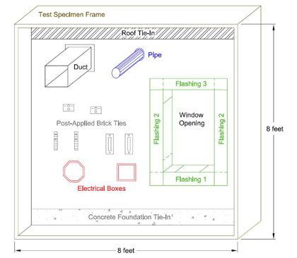
ASTM E 2357 overcomes this limitation by defining a uniform method of evaluating the entire assembly. The standard defines a specimen wall assembly that is a realistic, 8-foot-square wall mock-up including a window opening with flashing and typical wall penetrations like pipes, vents and ties, as well as roof and concrete foundation tie-ins (see figure below). This provides a realistic evaluation of air barrier assembly performance and helps verify that the components are compatible with each other.

Diagram of specimen wall for testing air barrier assembly performance, as specified in ASTM E 2357.
The standard also defines a specific test procedure. The wall specimen is mounted in a well-sealed test chamber with an air supply that allows application and measurement of both positive and negative air pressure differentials across the wall structure in three stages:
- Sustained Load – 600 Pa (12.5 psf), equivalent to a 70 mph wind speed for 1 hour.
- 2000 Cyclic Loads – 800 Pa (16.7 psf), equivalent to an 81 mph wind speed for 3 seconds each.
- Wind Gusts – 1200 Pa (25 psf), equivalent to a 99 mph wind speed for 3 seconds.
These stages are intended to simulate air pressures typically experienced by buildings, including: stack pressure (difference in pressure between the bottom and top of the air column), wind pressure (creating positive pressure on one side of the building and negative pressure on the other), and fan pressure (created by HVAC or fan systems within the building).
Following each stage, the air leakage rate—or air permeance—of the wall assembly Is measured at pressure differentials of 25, 50, 75, 100, 150, 250 and 300 Pa; the calculated leakage at 75Pa is reported. Air barrier deflection is then measured. To comply with the International Energy Conservation Code (IECC), the air barrier assembly may not exhibit air permeance greater than 0.2 liters per second/square meter at 75 Pa pressure (0.04 cfm/ft.2 at 1.57 lb/ft2).
Compliance
ASTM E 2357 has been adopted by the Air Barrier Association of America (ABAA) as a key element of its acceptance criteria. As noted, the data generated by this standard test method is important to verify an air barrier assembly’s compliance with the IECC, a critical consideration given today’s focus on energy efficiency.
Related
PERM-A-BARRIER® Air Barrier System
Overview The PERM-A-BARRIER® portfolio offers both permeable and non-permeable solutions to meet the range of factors on a given project, including regional climate, wall de...
READ MOREJanuary 10, 2018
ASTM E 96: Testing Water Vapor Transmission through Materials
Selecting the right air barrier Understanding how much water vapor can pass through various materials used in wall assemblies is an important factor in selecting an air barrier to meet a specific wal...
READ MORESeptember 21, 2017
Stay dry: Why rain resistance matters when choosing an air barrier
Imagine your contractor's crew has just spent the day installing a fluid-applied air barrier on the exterior wall of your building, taking care to get a nice, consistent thickness to ensure proper per...
READ MORENovember 10, 2017
To Protect Building Durability, Focus on Air Barrier Durability
As discussed in a previous blog post, minimizing air leakage through the building envelope is important to protecting the long-term durability of a structure. Uncontrolled air flow introduces moisture...
READ MORESeptember 25, 2017
To maximize indoor air quality, minimize air leakage
It's a four-letter word no building owner wants to hear: mold. Yet, it's an all-too-common occurrence in buildings where moist air accumulates on vulnerable wall components, including insulation, ext...
READ MORETags
- Air & Vapor Barriers
- Architects
- Building Envelope Solutions
- Consultant
- Contractor
- Distributor
- Energy efficient solutions
- Engineer
- PERM-A-BARRIER
- Subcontractor