Crack Injection Procedures
Polyurethanes, as well as some acrylics and acrylates, are commonly installed into joints and cracks for the purpose of stopping leaks and sealing voids. This process is very reliable if these steps are followed:
Step 1: Identify and prepare the crack surface
This step helps to identify the characteristics of the crack to be injected.
- Use a wire brush to physically remove mineral deposits and dirt
- Water can be used to help clean the area
- If severe deposits exist, a chemical cleaner can be used, but MUST be neutralized prior to continuing.
- If it is a wide crack or high water flows are encountered, it will be necessary to seal the surface of the crack with a surface sealing material; (example: hydraulic cement, epoxy gel, or oakum saturated with polyurethane grout).
- The surface sealing can be done before or after drilling the injection holes.
Step 2: Mark port spacing
Part A—Calculate Port Distance From Crack
Unlike epoxies, polyurethanes are injected at an angle to intersect the crack at its midpoint, allowing for a complete seal.
To intersect a crack at its mid-point, drill at a 45 degree angle at a distance of one half the thickness of the wall. For example with a 12 inch thick wall, drill holes 6 inches from crack.
Drilled holes should intersect the crack or joint at its mid-point. Grout can then easily travel towards the front and back of the crack, filling other voids along the way.
Injection pressure and the expansion pressure of the foam cause the resin to seal the entire width of the substrate, and secondary cracks, as well as various other defects that may be present, ensuring a water tight seal.
Part B—Polyurethanes are injected to allow port-to-port travel. Port spacing is determined by the width of the crack.
- The narrower the crack, the closer the ports must be placed.
- The wider the crack the further apart they can be placed.
Ports are alternated from side to side to ensure intersection of the crack as well as to prevent a weak side of the crack.

Figure 1. Preparing the crack..
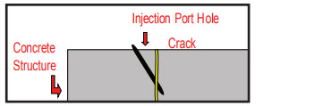
Figure 2. To drill at a 45° angle, drill distance must be ½ the thickness of the wall.EX. 12 inch thick wall = drill holes 6 inches from crack

Figure 3. The lines show the port spacing. Closer at the bottom where the crack in tighter, further apart at the top where the crack widens.

Figure 4. Drill hole pattern.

Figure 5. Installation of packers

Figure 6. Drill pattern on overhead crack.
Step 3. Drilling the injection holes
The standard drill hole will be 1/2” or 5/8” in diameter, proportional to the packer being used.
- Drill at a 45 degree angle, alternating sides, as described above.
- Flush drill holes with water to remove dust and debris before inserting packer.
Step 4. Install injection ports or packers
A variety of packers that are suited for various types of applications are available.
- Place the selected packer in the drilled 1/2” or 5/8” diameter hole so that the top of the sleeve is just below the concrete surface.
- Tighten by a ratchet, socket or open-end wrench by turning clockwise until firm and secure.
- Packers or injection ports are supplied with a one-way ball valve or check valve.
Step 5. Prepare injection equipment
When using grouts that are water activated, it is necessary to have two pumps on site. One for water, the other for grout. Never use the water pump for grouting. Always ensure that water is never introduced into the grout pump.
Using a washing agent, flush the grout pump prior to injection and immediately after injection.
Flushing the pump eliminates the moisture in the pump and hoses and lubricates the system.
Step 6. Flush crack
Flushing the crack will ensure that the crack is wet enough to react the grout when it is introduced into the crack.
- Using the water pump, attach the water pump hose to the zerk connector.
- Turn the pump on and inject the crack or joint.
- Continue until water flushes crack clean. Once the drilled holes and the crack have been flushed, the packers can be removed so that migration of the injected grout can be monitored.

Figure 7. Two pumps: one for water and one for grout.
Step 7. Injection of Grouts
Depending on the nature of the crack, different polyurethane grouts can be injected. Please review the technical data for the proper selection of the grout to be used. Always read and have on site the MSDS for the products used. The following information will provide help in making the product selection.
Cut PURe and CFL PURe are used for non-moving (static) cracks and gushing water.
Flex LV PURe and Flex SLV PURe are used for moving (dynamic) cracks or construction joints above and below grade Sealfoam PURe is used for moving cracks in continuously moist/ wet environments.
Superflex or Superflex AR (methacrylic acrylate copolymer grouts) are used for extremely tight hairline cracks and spider cracking in moving and non-moving structures.
Remember: always flush the grout injection pump with washing agent before starting the injection process.
Begin the injection at the lowest packer installed on a vertical crack, or at the first packer flushed for a horizontal crack. During injection, you will notice that the Grout displaces water from the crack.
- Continue injecting until grout appears at the adjacent packer hole.
- Stop pumping and reinstall the packer in the adjacent hole, tighten and begin inject ing on it.
- Continue this process until 3-4 packers have been grouted.
- Disconnect and go back to the first packer and inject all the ports for the second time. Some of the ports may take additional grout and further densify the material in the crack.
- Continue this process until the length of the prepared crack is injected.
Note: Injection pressure will vary from 200 psi to 2500 psi depending on the width of the crack, thickness of concrete and condition of concrete.

Figure 8. Flushing crack with water.

Figure 9. Grout travel up vertical crack.

Figure 10. Port-to-port continuity.

Figure 11. Port to port grout show

Figure 12. Dry, grouted joint.

Figure 13. Always flush lines thoroughly.
Step 8. Re-inject packers with water
- Re-inject each packer with a small amount of water. This will ensure a full reaction of all resin in the drill holes
Step 9. Surface cleaning and repair
- Use scraper to remove partially cured resin from the surface.
- Fully cured resin can be removed through mechanical methods including grinding.
- Let grout fully cure inside injected areas.
- Cut packers flush with surface or remove packers completely.
Repair surface with appropriate material. Inspect the pumping equipment to ensure proper operation and that the hoses that will be used for injection are not crimped, frayed or in need of repair.
Step 10. Equipment cleaning
- Flush grout pump immediately with WASHING AGENT until resin in line is displaced by cleaner. Resin should be washed out into a waste bucket.
- Circulate WASHING AGENT through pump for 10-20 minutes by connecting intake and outlet in an open five gallon pail.
- Flush lines one last time with fresh WASHING AGENT to remove contaminants.
- Store pump and hoses with vegetable oil or other environmentally friendly lubricant to protect lines and fittings.
Step 11. Safety
A safety meeting should be held with the entire injection crew. An overview of the procedure should be discussed and the data sheets and MSDS should be reviewed for all of the products that will be used during the injection process.
Safety equipment should be reviewed and care should be taken to insure that all members of the crew are properly outfitted with the appropriate safety equipment. In addition to the safety equipment required for the job site, each member of the injection crew should have, rubber boots, Tyvek suits, rubber gloves, safety goggles or full-face shields.
Step 12. Equipment requirements supply list
- Airless Pump Model 395st or Equivalent--MUST HAVE SEPARATE PUMPS FOR GROUT AND WATER.
- Injection packers or bang in ports.
- Face shields and safety glasses.
- Latex or nitrile Gloves.
- Plastic 5 gallon Buckets “Clean” - 5 each
- Trash bags for lining buckets – optional. (Allows buckets to be reused)
- Roll of 4 or 6 mil poly sheeting.
- DE NEEF® Washing Agent for cleaning pumps.
- Chemical Grout (and catalyst if required).
- Good quality heavy-duty drill.
- Drill bit 12 -18 inches long corresponding with packer size.
- DE NEEF® Denepox Rapid Gel Epoxy in cartridges or other suitable material for surface sealing cracks.
- Dual cartridge caulking gun.
- Duct tape, oakum, and rags.
- Hard hats, ear plugs, and any other PPE required by the facility owner.
- SDS for all products on site.
Note: Our recommendations for use of the product are based upon many years of actual field application and are believed to be reliable and should be used as a guide. This procedure may be modified to suit the actual jobsite conditions. However, since field conditions vary widely, the user must determine the suitability of the product for the particular use and specific method(s) of application.
gcpat.com | North America Customer Service: +1 (877) 423 6491
We hope the information here will be helpful. It is based on data and knowledge considered to be true and accurate and is offered for consideration, investigation and verification by the user, but we do not warrant the results to be obtained. Please read all statements, recommendations and suggestions in conjunction with our conditions of sale, which apply to all goods supplied by us. No statement, recommendation, or suggestion is intended for any use that would infringe any patent, copyright, or other third party right.
DE NEEF is a trademark, which may be registered in the United States and/or other countries, of GCP Applied Technologies Inc. This trademark list has been compiled using available published information as of the publication date and may not accurately reflect current trademark ownership or status.
© Copyright 2018 GCP Applied Technologies Inc. All rights reserved.
.
In Canada, 294 Clements Road, West, Ajax, Ontario, Canada L1S 3C6.
GCP Applied Technologies, 20 Moores Road, Malvern, PA 19355, USA.
GCP Canada, Inc., 294 Clements Road, West, Ajax, Ontario, Canada L1S 3C6
This document is only current as of the last updated date stated below and is valid only for use in the United States. It is important that you always refer to the currently available information at the URL below to provide the most current product information at the time of use. Additional literature such as Contractor Manuals, Technical Bulletins, Detail Drawings and detailing recommendations and other relevant documents are also available on www.gcpat.com. Information found on other websites must not be relied upon, as they may not be up-to-date or applicable to the conditions in your location and we do not accept any responsibility for their content. If there are any conflicts or if you need more information, please contact GCP Customer Service.
Last Updated: 2026-06-23
https://gcpat.com/en/solutions/products/de-neef-waterproofing-injection-solutions/tb-0055-standard-application